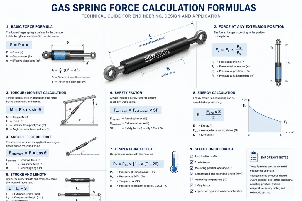
Technical Reference — Force Calculation
Gas Spring Force
Calculation Formulas
The full set of equations engineers actually use to size a gas spring — moment balance, pressure-area sizing, progression ratio, stroke geometry, damping and temperature derating — each with a worked example in N and lbf.
What’s on this page: a decision guide for picking the formula that governs your case, the master moment-balance equation worked end to end, the complete 40-formula reference grouped by category, and the two factors most calculators ignore — paired-spring matching and temperature derating. Every value is given in both N and lbf.
40
Engineering Formulas Covered
±5%
Newtone Force Tolerance
20–7500 N
Manufacturing Range (4–1686 lbf)
−40 / +100°C
Operating Temperature Range
Which Formula Actually Governs Your Case?
Most guides hand you a single equation and assume every application is a hinged lid. They aren’t. Before you calculate anything, identify the dominant physics of your application — that decides which formula leads. Use this as a quick router.| Your application | Governing relationship | Why this one |
|---|---|---|
| Hinged lid / top-opening panel | Moment balance F = (W·Lg·cos φ)/(n·r) | Force is set by leverage about the hinge, not by weight alone. |
| Straight vertical lift (sliding hatch) | F ≥ W ÷ n | No lever arm — the springs simply share the dead weight. |
| “Why does a thicker rod push harder?” | F = ΔP·A with A = π·d²/4 | Force scales with rod area, so with the square of diameter. |
| Soft-close / controlled motion | F_damp = c·v | Damping is velocity-dependent and separate from static force. |
| Cold store, engine bay, outdoor | F_T ≈ F₂₀·[1 + 0.003·(T − 20)] | Force falls with temperature — size at the operating temperature. |
| Two or more springs on one panel | F_each = F_total/n + ±5% matching | Even lift needs matched force, not just the right total. |
The Master Equation: Moment Balance, Worked End to End
For any hinged panel, the spring has to generate enough torque about the hinge to balance the torque gravity applies to the panel. Set those two moments equal and solve for force. This is the equation to reach for first, because it is always valid for a pivoting panel.Required force per spring
F = (W × Lg × cos φ) ÷ (n × r)
W = panel weight (N) • Lg = hinge-to-centre-of-gravity distance • φ = load-arm angle above horizontal • r = spring’s perpendicular moment arm • n = number of springs
Worked example — a 14 kg (31 lb) access panel, 700 mm (28 in) long, held horizontally, on two springs:
W = m × g = 14 × 9.81 = 137.3 N (31 lbf)
Lg = 700 ÷ 2 = 350 mm (13.8 in) r = 140 mm (5.5 in) φ = 0° → cos φ = 1
F = (137.3 × 350 × 1) ÷ (2 × 140) = 171.7 N (39 lbf) per spring
Add a 1.2 safety factor → F_design = 171.7 × 1.2 = 206 N (46 lbf) per spring
The Complete Gas Spring Formula Library (40 Relationships)
Here is the full set of gas spring force calculation formulas, grouped by what each does: static force and geometry, the internal gas physics, force progression, stroke and packaging, damping, and temperature and life. Pick the lead formula that matches your application, then use the supporting ones — safety factor, progression ratio, temperature correction — to refine it.| # | Formula | Use it when |
|---|---|---|
| A — Static force & geometry (hinged / lever applications) | ||
| 1 | F = (W·Lg·cos φ)/(n·r) | Master sizing for any hinged or lever panel. |
| 2 | T_lid = W·r_CG·cos φ | The load-side moment to overcome at a hold-open angle. |
| 3 | T_spring = F·r_perp | Support-side moment; set T_spring ≥ T_lid to hold. |
| 4 | F = T_lid/(n·r_perp) | Force per spring straight from the torque balance. |
| 5 | W = m·g | Convert mass to weight (g = 9.81 m/s²). |
| 6 | F ≈ (m·9.81·LAF)/n | Quick top-hinged estimate (LAF ≈ 0.5–0.7); planning only. |
| 7 | F = (W·L)/d | Mounting-distance form; a larger d lowers the force needed. |
| 8 | F_design = F·SF | Apply a 1.1–1.3 safety factor (higher for wind/snow loads). |
| 9 | r_CG = L_panel/2 | Centre of gravity of a uniform panel. |
| 10 | F_each = F_total/n | Split the balanced load across n springs. |
| 11 | r = d·sin ψ | Effective moment arm; force is lowest when strut ⟂ panel. |
| 12 | F_close = (n·F1·r)/L_lid | Residual hand force to close a fully-open panel. |
| 13 | Recompute r_CG from real CoG | Off-centre hinge; the moment balance still governs. |
| B — Internal physics (pressure, area, gas law) | ||
| 14 | F = ΔP·A | Force from the pressure differential across the rod. |
| 15 | A = π·d²/4 | Rod area; doubling diameter quadruples force. |
| 16 | ΔP ≈ P_internal | Valid simplification for normal ambient use. |
| 17 | P1·V1 = P2·V2 | Boyle’s law; pressure rises as the rod enters. |
| 18 | P2 = P1·(V1/V2) | Pressure — and force — at any stroke position. |
| 19 | ΔV = A_rod·stroke_inserted | Volume the entering rod displaces. |
| 20 | A_return = π·(D²−d²)/4 | Effective return-stroke area (damper context). |
| 21 | F = P·π·D²/4 | Theoretical full-bore cylinder force. |
| 22 | F_eff = P·A − F_friction − F_seal | Net force after friction (commonly 3–20%). |
| C — Force progression & spring rate | ||
| 23 | K = P2/P1 | Progression ratio (typically 1.05–1.8). |
| 24 | Force Ratio = P2/P1 | Confirm the rising feel toward closed (1.1–1.6 typical). |
| 25 | F = k·X | Local spring rate; small and roughly constant over the stroke. |
| 26 | Size from P1 | Use the extended-position force as the baseline. |
| 27 | ΔF = P2 − P1 = F1·(K−1) | Extra force gained as the rod is pushed in. |
| D — Stroke, length & packaging geometry | ||
| 28 | Stroke = Extended − Compressed length | The basic travel definition. |
| 29 | L_compressed ≥ Stroke + body allowance | The cylinder must house stroke plus seals and fittings. |
| 30 | Extended length + pivot geometry | Reach check — full open without bottoming. |
| 31 | X = L_extended − L_closed | Travel of the moving pivot, closed to open. |
| 32 | Keep line of action off the hinge | Over-centre avoidance — or the panel traps. |
| 33 | Mount ≈ ⅓ panel length from hinge | First-iteration mount point, then refine with #1. |
| E — Damping & motion control | ||
| 34 | F_damp = c·v | Viscous damping, proportional to rod velocity. |
| 35 | End-of-stroke oil metering | Slows the rod near full extension; needs rod-down. |
| 36 | Speed ∝ orifice size | Larger orifice faster, smaller orifice slower. |
| 37 | Damping fails below oil pour point | Cold-environment material-selection check. |
| F — Temperature & life | ||
| 38 | F_T ≈ F₂₀·[1 + 0.003·(T−20)] | Force changes ≈0.3% per °C — size at operating temp. |
| 39 | P_T/P_0 = T_T/T_0 | Gay-Lussac (absolute K); the basis of #38. |
| 40 | Service years ≈ Cycles ÷ per-day ÷ 365 | Life framing against the dominant wear driver. |
The Two Factors Most Calculators Skip
1. Paired-spring matching — tolerance beats absolute force
When two springs share a panel, the number that matters most isn’t the rating — it’s how closely the two match. Picture two springs both labelled 200 N (45 lbf). Built to a loose ±15% commodity tolerance and drawn from different batches, one can land at 230 N (52 lbf) and the other at 170 N (38 lbf): a 60 N (13 lbf) imbalance across the panel. That difference twists the panel as it opens, loads one hinge far harder than the other, and shows up months later as uneven wear and a door that no longer sits square. Held to ±5% and matched from a single batch, the same pair differs by at most about 20 N (4.5 lbf) — small enough to lift evenly. This is why we batch-match paired springs on request rather than shipping two units that merely carry the same label.2. Temperature derating — the formula winter exposes
Gas spring force isn’t constant across the seasons. Because the force comes from pressurised gas, it tracks temperature at roughly 0.3% per °C (formula #38). Take the 206 N (46 lbf) design force from the worked example: at −20°C (−4°F) it delivers F_T = 206 × [1 + 0.003 × (−40)] = 181 N (41 lbf) — about 12% weaker. A panel that holds open perfectly in a summer workshop can sag or drift shut in a winter yard, and the instinct to “just add force” then leaves it slamming in summer. The correct move is to size at the coldest operating temperature in the first place. For outdoor and unheated applications we specify HNBR seals as standard for their UV and ozone resistance, and a black-nitrided rod (900–1000 HV) to keep the seal surface intact across the full −40°C to +100°C range.⚠ The most common sizing mistake: calculating from weight alone and ignoring geometry. Two panels of identical weight can need forces that differ by a factor of two, purely because of hinge offset and mounting position. Always run the moment balance with the actual r and φ for your design — the scale tells you the load, not the force.
A few years ago an OEM building a new equipment enclosure sent us drawings with a force they’d estimated at around 300 N (67 lbf) per spring — reasonable-looking for the panel weight. Running the moment balance on their real geometry, with the hinge offset and hold-open angle they’d drawn, put the actual requirement closer to 190 N (43 lbf). Had they tooled the design around the 300 N guess, every panel would have self-opened and hammered its hinges from day one. We flagged it before first article, supplied the corrected value, and the panel held cleanly. The arithmetic took ten minutes; it saved a tooling revision.
Why Engineers Bring the Calculation to Newtone
We’re a manufacturer, not a distributor. Every spring is built in our own facility in Turkey, so the force tolerance, seal compound and rod finish that these formulas assume are things we actually control.±5% Force Tolerance
Tighter than the ±10–15% of commodity suppliers — the difference that makes paired-spring matching work.
Free Force Calculation
Send your panel weight, hinge offset and angle; we return a force value and stroke recommendation.
Built for the Temperature Range
HNBR seals and a black-nitrided rod hold up from −40°C to +100°C (−40°F to +212°F).
Full Custom Configuration
Force, stroke, body diameter, end fittings and rod finish — each specified independently per order.
Batch-Matched Pairs
Springs paired from the same production run so both sides of a panel lift evenly.
OEM & Aftermarket — 60+ Countries
New-platform integration and replacement supply from one product platform, with a reply within 5 business hours.
Frequently Asked Questions
What is the basic formula to calculate gas spring force?
For a hinged panel, gas spring force is set by a moment balance about the pivot: F = (W × Lg × cos φ) ÷ (n × r). The panel’s weight, its hinge-to-centre-of-gravity distance, the hold-open angle, the number of springs and the spring’s moment arm all feed into it. It is the single most useful starting formula, but the governing equation changes for straight lifts, pressure-area sizing or damping.
Is multiplying weight by 9.81 to get Newtons enough to size a gas spring?
No. Converting mass to weight with W = m × 9.81 only gives the load in Newtons; it does not give the spring force. The force each spring must produce also depends on where it is mounted relative to the hinge, the hold-open angle and how many springs share the load. Two panels of identical weight can need very different forces purely because of geometry.
Why does my gas spring feel weaker in cold weather?
Gas spring force drops with temperature at roughly 0.3% per °C, because the pressure inside the cylinder falls as the gas cools. A spring sized at 20°C can deliver around 12% less force at −20°C, which is why a panel that holds open in summer can sag or close in deep winter. The fix is to size at the coldest operating temperature, not at bench temperature.
How do I match two gas springs on the same panel?
Use a tight force tolerance and the same production batch. Two springs nominally rated the same but built to ±15% can differ by enough to twist the panel and overload one hinge. Newtone holds force to ±5% and pairs springs from the same batch on request, so both sides lift evenly.
Does a thicker piston rod give more force?
Yes. Gas spring force follows F = ΔP × A, and the rod area is A = π × d² ÷ 4, so force scales with the square of rod diameter at the same pressure. Doubling the rod diameter roughly quadruples the force. That is why force is changed by rod and pressure together, not by pressure alone.
Conclusion
Sizing a gas spring well comes down to choosing the formula that matches your geometry, working it with consistent units, and respecting the two factors most calculators leave out — paired-spring matching and temperature derating. The moment balance handles the majority of hinged panels; the rest of the library is there for the cases where a straight lift, a pressure-area question, a damping requirement or a cold-weather correction takes over. A calculator gives you a number. Understanding which equation produced it, and what it assumes, is what stops you from tooling around a wrong guess. That’s the difference between a panel that works for ten years and one that becomes a recurring service call. If you’d rather hand off the arithmetic, send us the panel weight, hinge offset and opening angle. We’ll run the calculation, recommend a force and stroke, and come back with a datasheet and quote — typically within 5 business hours.Get Your Force Calculated
Share your dimensions and we’ll do the moment balance for you — free force recommendation, stroke selection, sample datasheet and competitive pricing.Email: info@newtonegs.com
Response: Within 5 business hours
Supply: OEM & Aftermarket — Global Export