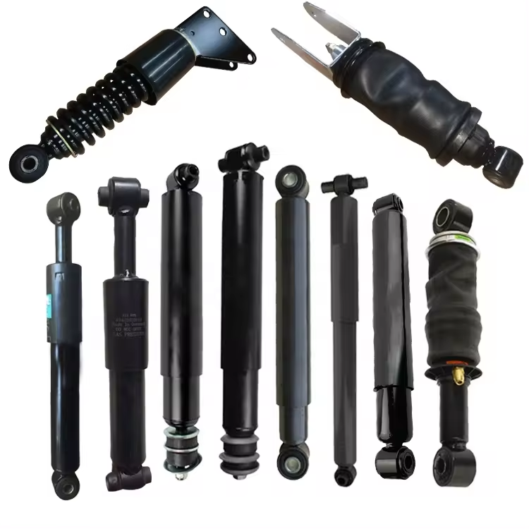
Hydraulic Dampers
Hydraulic dampers are motion control devices designed to regulate the speed of moving components, reduce sudden movement and provide smooth, controlled deceleration.
Hydraulic Dampers for Controlled Motion & Smooth Deceleration
Unlike conventional gas springs, which primarily generate force to assist lifting, opening or counterbalancing, a hydraulic damper is primarily used to control movement and dissipate kinetic energy.
At Newtone Gas Springs, we manufacture hydraulic dampers for industrial and OEM applications where uncontrolled or excessively fast movement could affect safety, comfort, equipment performance or component life. Depending on the application, damping can be provided during compression, extension or in both directions, allowing the motion characteristics to be matched to the required movement.
Hydraulic dampers can be used to control doors, covers, access panels, machine components, guards, adjustable equipment and many other moving assemblies. By controlling the velocity of the moving component, the damper can help prevent sudden closing, uncontrolled opening, impact at the end of travel and undesirable oscillation.
For applications requiring different motion characteristics, Newtone can provide compression hydraulic dampers, extension hydraulic dampers, bidirectional hydraulic dampers and adjustable hydraulic dampers. The appropriate solution depends on the direction of movement that must be controlled, the moving mass, stroke, installation geometry and desired operating speed.
What Is a Hydraulic Damper?
A hydraulic damper is a sealed motion control device in which hydraulic fluid is forced through calibrated flow passages as the piston moves inside the cylinder. This controlled restriction of fluid flow creates resistance to movement, allowing the damper to regulate the speed of the connected component.
The damping resistance is generated by the movement of hydraulic oil through the internal flow-control system. Instead of allowing the connected component to accelerate or move freely, the damper absorbs and dissipates part of the movement energy, producing a smoother and more controlled motion.
The required damping behaviour can vary significantly between applications. Some systems require resistance primarily while the piston rod is being compressed, while others require controlled movement during extension. Applications requiring controlled movement in both directions can use a dual-direction or bidirectional hydraulic damper.
Hydraulic Damper vs. Gas Spring: What Is the Difference?
Although hydraulic dampers and Standard Gas Springs can have a similar external appearance, they perform fundamentally different functions within a motion control system.
| Feature | Hydraulic Damper | Gas Spring |
|---|---|---|
| Primary Function | Controls movement speed and provides damping. | Provides force for lifting, supporting and counterbalancing. |
| Operating Principle | Uses controlled hydraulic fluid flow to create resistance to movement. | Uses compressed gas to generate extension force. |
| Motion Control | Can control compression, extension or both directions depending on the design. | Primarily provides controlled force during extension and compression. |
| Typical Objective | Reduce speed, soften movement, control deceleration and minimise impact. | Assist opening, lifting, holding and counterbalancing a moving load. |
| Typical Applications | Machine guards, covers, access panels, industrial mechanisms and controlled-motion assemblies. | Doors, lids, hatches, covers and other applications requiring lifting or counterbalancing assistance. |
In some applications, a gas spring and hydraulic damper can perform complementary roles within the same mechanism: the gas spring provides the required supporting or lifting force, while the hydraulic damper controls the speed of movement. The correct configuration depends on the mechanical requirements and geometry of the application.
How Do Hydraulic Dampers Work?
A hydraulic damper controls motion by creating resistance to the movement of a piston through hydraulic fluid. Inside the sealed cylinder, the piston separates working chambers filled with hydraulic oil. As the piston rod moves in or out, the fluid is forced through precisely defined internal passages, valves or orifices. The restriction of this fluid flow generates the damping force that slows and controls the connected component.
Rather than stopping movement abruptly, the hydraulic damping process dissipates kinetic energy and regulates the velocity of the moving component. This makes it possible to transform rapid, uncontrolled or impact-producing movement into a smoother and more predictable motion.
The amount and direction of damping depend on the internal design of the damper. A hydraulic damper can be configured to provide resistance mainly during compression, mainly during extension, or during both compression and extension. Adjustable versions can provide additional control where the required damping behaviour needs to be fine-tuned for the application.
Inside a Hydraulic Damper
Although the exact internal configuration can vary according to the damper design and application requirements, the fundamental hydraulic damping principle is based on controlled fluid displacement.
| Component | Function |
|---|---|
| Cylinder | Contains the hydraulic fluid and internal damping components while providing the working chamber for piston movement. |
| Piston Rod | Transfers the movement of the application to the internal piston assembly. |
| Piston | Moves through the hydraulic fluid as the piston rod extends or compresses. |
| Hydraulic Fluid | Transfers energy through the internal system and creates damping resistance when its flow is restricted. |
| Valves / Flow Passages | Control how quickly hydraulic fluid can move between working areas, directly influencing the damping characteristics. |
| Sealing System | Maintains the hydraulic fluid inside the damper and supports reliable operation throughout repeated movement cycles. |
How Is Damping Force Generated?
When the piston moves inside the cylinder, hydraulic oil must move from one working area to another. Because the fluid cannot pass freely, it is forced through restricted flow paths. This creates a pressure difference across the piston and generates resistance against its movement.
In practical terms, the faster the application attempts to move, the more important the hydraulic flow characteristics become in determining how the motion is controlled. The internal valve and flow configuration can therefore be engineered according to the required operating behaviour rather than simply allowing the connected component to move without resistance.
This principle allows an industrial hydraulic damper to control movement progressively and reduce the mechanical shock that could otherwise occur when a component accelerates, closes or reaches the end of its travel too quickly.
Compression, Extension and Bidirectional Damping
The direction in which resistance is required is one of the most important parameters when specifying a hydraulic damper. The correct damping configuration depends on which part of the application’s movement needs to be controlled.
Compression Damping
With compression damping, the primary damping resistance is generated as the piston rod moves into the cylinder. This configuration is suitable when the application needs controlled deceleration or restricted speed during the closing or compression movement.
Extension Damping
With extension damping, the primary resistance is generated as the piston rod moves out of the cylinder. This configuration is used when the outward or opening movement of the application needs to be slowed and controlled.
Bidirectional Damping
A bidirectional hydraulic damper, also referred to as a dual-direction or two-way hydraulic damper, provides damping resistance during both extension and compression. This is useful when controlled movement is required throughout both directions of the operating cycle.
Why Hydraulic Damping Improves Motion Control
Without appropriate damping, gravity, external forces or the dynamics of the mechanism can cause a component to move faster than intended. This can result in sudden closing, rapid opening, impact, vibration, noise or unnecessary mechanical stress on the surrounding structure.
A correctly selected hydraulic motion damper regulates this movement instead of simply restricting it mechanically. This can provide smoother operation, improve user control and reduce impact loads transferred to hinges, brackets, mounting points and other components within the assembly.
Where an application also requires lifting or counterbalancing force, hydraulic damping can be combined with a Standard Gas Spring. In this type of system, the gas spring provides the supporting force while the hydraulic damper performs the separate function of controlling movement speed.
Types of Hydraulic Dampers
Hydraulic dampers can be engineered to control movement during compression, extension or both directions of travel. Selecting the correct damping direction is essential because the damper must provide resistance during the specific phase of movement that needs to be controlled.
At Newtone Gas Springs, hydraulic damper solutions can be configured according to the required direction of damping, operating characteristics and application geometry. The main configurations include Compression Hydraulic Dampers, Extension Hydraulic Dampers, Bidirectional Hydraulic Dampers and Adjustable Hydraulic Dampers.
Compression Hydraulic Dampers
A compression hydraulic damper provides its primary damping resistance when the piston rod moves into the cylinder. During this compression movement, hydraulic fluid is forced through the internal flow-control system, creating resistance that regulates the speed of the connected component.
This configuration is particularly useful when a moving component needs to be slowed during a closing, lowering or inward movement. Instead of allowing the mechanism to accelerate freely and reach the end of its travel with excessive speed, compression damping provides controlled resistance throughout the required portion of the movement.
Typical applications can include covers, access panels, machine components, guards and other mechanisms where the compression stroke corresponds to the movement that must be controlled.
Extension Hydraulic Dampers
An extension hydraulic damper provides its primary damping resistance as the piston rod moves out of the cylinder. The internal hydraulic system regulates fluid flow during extension, creating controlled resistance against the outward movement.
Extension damping is suitable when the opening, rising or outward movement of a component needs to be controlled. This can be especially important when gravity, another mechanical element or an external force could otherwise cause the mechanism to extend too rapidly.
By controlling extension velocity, the damper can help provide smoother movement and reduce sudden acceleration, impact and unnecessary loads on surrounding mounting components.
Bidirectional Hydraulic Dampers
A bidirectional hydraulic damper provides damping during both compression and extension. These products may also be described as dual-direction hydraulic dampers or two-way hydraulic dampers.
Bidirectional damping is particularly useful when both phases of the application’s movement need to be controlled. Instead of allowing one direction to move relatively freely, resistance is generated during both inward and outward piston rod movement.
The damping characteristics do not necessarily have to be identical in both directions. Depending on the internal configuration and application requirements, the required motion behaviour can be engineered according to how the mechanism needs to move during extension and compression.
Adjustable Hydraulic Dampers
An adjustable hydraulic damper allows the damping behaviour to be adjusted within the design range of the product. This provides additional flexibility when the optimum movement speed or resistance cannot be determined accurately before the damper is installed in the actual application.
Adjustability can be particularly valuable during prototype development, machine setup or applications where different operating conditions require the movement characteristics to be fine-tuned. Instead of relying on a single fixed damping characteristic, the system can be adjusted to achieve a more appropriate motion response for the equipment.
Once the desired operating behaviour has been established, the selected damping setting can provide a useful reference when defining the final specification for an OEM application.
Which Hydraulic Damper Type Should You Choose?
| Damper Type | Damping Direction | Typical Requirement |
|---|---|---|
| Compression Hydraulic Damper | Primary damping during piston rod compression | Controlling closing, lowering or inward movement |
| Extension Hydraulic Damper | Primary damping during piston rod extension | Controlling opening, rising or outward movement |
| Bidirectional Hydraulic Damper | Damping during compression and extension | Controlling movement throughout both directions of travel |
| Adjustable Hydraulic Damper | According to the damper configuration | Applications requiring fine-tuning of the damping behaviour |
Choosing Damping Direction According to the Application
The correct damper type should be determined by analysing the actual movement of the equipment rather than selecting a product based only on dimensions. Engineers should identify which direction needs to be controlled, what causes the movement, how fast the component would move without damping and what motion behaviour is required.
For example, if gravity causes a cover to close too quickly, damping may primarily be required during the closing direction. If another force causes a component to open rapidly, the opposite damping direction may be required. Where both movements need controlled speed, a bidirectional solution may be more appropriate.
Applications requiring both lifting assistance and speed control should also distinguish between the two functions. A Standard Gas Spring can provide lifting or counterbalancing force, while the hydraulic damper can be specified separately to control the movement velocity.
Applications of Hydraulic Dampers
Hydraulic dampers are used in applications where the speed of a moving component must be controlled to achieve smoother, safer and more predictable motion. They are particularly valuable where gravity, external forces, stored mechanical energy or the dynamics of the mechanism could otherwise cause rapid opening, closing, lowering or extension.
Because hydraulic dampers can be configured for compression damping, extension damping or bidirectional damping, they can be adapted to a wide range of industrial and OEM motion control requirements. The correct solution depends on the direction of movement, moving mass, stroke, operating velocity, mounting geometry and environmental conditions of the application.
Industrial Machinery & Automation
Machine guards, access panels and moving mechanisms requiring regulated speed and reduced impact.
Machine Guards, Covers & Access Panels
Controlled closing and opening to protect hinges, brackets and mounting points from sudden loads.
Automotive & Transportation
Covers, compartments and access mechanisms requiring a smoother, more controlled operating feel.
Medical & Rehabilitation Equipment
Smooth, predictable adjustment of moving sections, covers and supports for user safety and comfort.
Furniture & Ergonomic Equipment
Controlled lowering, opening or closing for adjustable furniture, seating and workstations.
Doors, Hatches & Movable Panels
Reduced velocity before end of travel to protect hinges and connections and smooth the motion.
The overview above summarises the application categories described below; it is a Claude-added visual summary and not part of the original text — happy to remove it if you’d prefer only the detailed sections.
Industrial Machinery & Automation
Industrial machinery often contains moving covers, guards, arms, mechanisms and access components that require controlled movement. An industrial hydraulic damper can regulate the speed of these components and reduce sudden acceleration or impact during operation.
In automated equipment, consistent motion can also be important for repeatability and mechanical durability. Hydraulic damping helps control movement rather than allowing components to travel freely until they reach a mechanical stop.
Typical Uses
- Machine guards and protective covers
- Industrial access panels
- Moving machine components
- Automation mechanisms
- Controlled opening and closing systems
- Equipment requiring smooth deceleration
Machine Guards, Covers & Access Panels
Heavy covers and access panels can accelerate quickly under gravity or other forces. This may result in sudden closing, hard impacts, excessive noise or increased loads on hinges, mounting points and surrounding structures.
A hydraulic damper can be integrated into the mechanism to control the critical direction of movement. Depending on the geometry, this may require a compression damper, extension damper or bidirectional hydraulic damper.
Where the cover also requires lifting assistance or counterbalancing, the damper can be used together with a Standard Gas Spring. In this arrangement, the gas spring provides supporting force while the hydraulic damper controls movement speed.
Automotive & Transportation Applications
Hydraulic damping can be used in specialised automotive and transportation mechanisms where controlled movement is required. Covers, compartments, access mechanisms and other movable assemblies may benefit from damping when uncontrolled movement could create impact, noise or an undesirable operating feel.
The damper specification should be matched to the actual movement characteristics of the mechanism, including the moving mass, available stroke, mounting points, operating speed and environmental conditions.
Medical & Rehabilitation Equipment
Medical and rehabilitation equipment can require smooth, predictable adjustment of moving components. Hydraulic dampers can help regulate the movement speed of adjustable sections, covers, supports or other mechanisms where sudden movement would be undesirable.
For these applications, the complete motion profile should be evaluated carefully. The damper must provide the required resistance without making normal adjustment unnecessarily difficult for the operator or user.
Furniture & Ergonomic Equipment
Adjustable furniture, specialised seating, workstations and other ergonomic equipment can incorporate hydraulic dampers to provide smoother movement and a more controlled user experience.
Depending on the design, damping may be required during lowering, opening, closing or throughout both directions of adjustment. Compact installation dimensions and the desired operating feel are often important considerations in these applications.
Doors, Hatches & Movable Panels
Doors, hatches and movable panels can become difficult to control when their geometry or weight causes rapid movement through part of the operating range. Hydraulic damping can regulate this movement and reduce the velocity before the component reaches the end of its travel.
This can help reduce impact loads on hinges, mounting brackets, end connections and the surrounding structure while creating a smoother opening or closing action.
Specialised OEM Motion Control Systems
Many OEM applications have motion characteristics that cannot be addressed effectively by selecting a hydraulic damper according to stroke and dimensions alone. The position of the centre of gravity, changing leverage through the movement, mounting geometry and desired operating speed can all influence the required damping behaviour.
For these applications, Newtone can evaluate the complete mechanism and develop a custom hydraulic damper according to the required damping direction, dimensions and operating characteristics. Adjustable hydraulic dampers can also be useful during prototype development where the optimum damping behaviour needs to be determined experimentally in the actual equipment.
Typical Hydraulic Damper Application Requirements
| Application Requirement | Hydraulic Damper Function |
|---|---|
| Component closes too quickly | Controls closing velocity and provides smoother deceleration. |
| Component opens too rapidly | Provides resistance in the opening direction to regulate movement speed. |
| Both directions require controlled movement | A bidirectional hydraulic damper can provide resistance during both extension and compression. |
| Impact occurs at the end of movement | Reduces movement velocity and the kinetic energy reaching the end of travel. |
| Equipment movement feels uncontrolled | Provides predictable hydraulic resistance for smoother motion. |
| Gas spring provides force but movement is too fast | The hydraulic damper can control velocity while the gas spring continues to provide lifting or counterbalancing force. |
| Required damping level is uncertain during development | An adjustable hydraulic damper can help determine the appropriate motion characteristics during prototype testing. |
How to Select the Right Hydraulic Damper
Selecting the correct hydraulic damper requires more than matching the stroke and overall dimensions. The damper must be matched to the actual dynamics of the application, including the direction of movement, moving mass, operating speed, installation geometry and required damping behaviour.
Two applications using components of similar weight may require very different damping characteristics if their mounting positions, centres of gravity, lever arms or movement speeds are different. For this reason, Newtone evaluates the complete mechanism when selecting or developing an industrial hydraulic damper for an OEM application.
Key Hydraulic Damper Selection Factors
| Selection Factor | Engineering Consideration |
|---|---|
| Damping Direction | Determine whether resistance is required during compression, extension or both directions of movement. |
| Stroke Length | The available damper stroke must be compatible with the movement range and mounting geometry of the application. |
| Extended & Compressed Length | The installation must provide sufficient space for the damper throughout its complete operating movement. |
| Moving Mass | The mass of the moving component contributes to the energy that must be controlled by the hydraulic damper. |
| Centre of Gravity | The position of the centre of gravity affects the torque acting on the mechanism and can significantly influence the required damping characteristics. |
| Mounting Geometry | Damper mounting points determine leverage and piston velocity throughout the movement and should therefore be considered as part of the damping calculation. |
| Operating Speed | The desired movement velocity is a fundamental parameter when defining the required hydraulic resistance. |
| Cycle Frequency | Applications operating frequently or continuously should be evaluated according to their expected duty cycle and thermal conditions. |
| Operating Temperature | Temperature can influence hydraulic fluid behaviour and should be considered when specifying a damper for demanding environmental conditions. |
| Mounting Connections | End fittings and mounting points should provide secure attachment while allowing the movement required by the application geometry. |
Determine the Required Damping Direction
The first question is simple but critical: which movement needs to be controlled?
If the component moves too quickly while the piston rod is entering the cylinder, a compression hydraulic damper may be required. If uncontrolled movement occurs while the piston rod is extending, an extension hydraulic damper may be more appropriate. When both directions need controlled resistance, a bidirectional hydraulic damper should be considered.
The direction should always be determined according to the actual damper installation. Terms such as opening and closing can be misleading because different mounting geometries can cause the piston rod to compress or extend during the same apparent movement.
Define Stroke and Installation Length
The required stroke length depends on the distance travelled between the selected mounting points as the mechanism moves through its operating range. Both the fully extended and fully compressed installation conditions should be checked.
The hydraulic damper should not be forced beyond its designed stroke or used as a mechanical stop unless the product has specifically been engineered for that function. Correct mounting geometry should allow the application to complete its intended movement without mechanically overloading the damper.
Evaluate Moving Mass and Centre of Gravity
Component weight alone is not sufficient to select the correct damper. The centre of gravity and its distance from the pivot point determine the torque acting on a rotating cover, panel or mechanism.
The effective load seen by the hydraulic damper can also change continuously as the application moves. A heavy panel with favourable leverage may require less damping than a lighter panel installed with a more demanding geometry.
Define the Desired Movement Speed
A hydraulic damper is selected to create the required motion behaviour, so the desired operating speed is an important part of the specification. The objective may be to prevent a cover from falling rapidly, slow an opening movement, reduce end-of-travel impact or provide controlled movement throughout the complete stroke.
For applications where the ideal damping level cannot be accurately predicted before installation, an adjustable hydraulic damper can be particularly useful during prototype testing. The damping behaviour can then be fine-tuned while observing the actual movement of the equipment.
Consider Mounting Geometry
Mounting position has a major influence on hydraulic damper performance. Changing the mounting point changes the mechanical leverage, piston rod travel and piston velocity relative to the movement of the application.
The damper should also be mounted so that the end connections can follow the required movement without excessive side loading. Suitable End Fittings and Mounting Brackets can help create the required articulation and installation geometry.
Consider Temperature and Operating Frequency
Hydraulic fluid characteristics are influenced by temperature. For applications exposed to significant temperature variations, the expected operating range should therefore be communicated during damper selection.
Operating frequency is also important. A mechanism operated occasionally has different duty requirements from industrial equipment performing repeated movement cycles. High cycle rates can influence the thermal behaviour of the damping system, making duty cycle an important consideration in demanding applications.
The six steps above (“How to Select the Right Hydraulic Damper”) were reformatted from numbered sections into the step-process component since they were already numbered 1–6 in the original text — no content was changed or added. Let me know if you’d rather keep them as plain headings.
What Information Should You Send Us?
For a new hydraulic damper application, providing information about the complete mechanism allows our engineering team to understand the required motion rather than selecting a product from dimensions alone.
| Application Information | Why It Helps |
|---|---|
| Moving Component Weight | Provides the basic mass that must be controlled. |
| Dimensions & Centre of Gravity | Helps determine the torque and changing mechanical load throughout the movement. |
| Required Stroke | Defines the necessary piston rod travel. |
| Extended / Compressed Length | Helps establish dimensional compatibility with the installation. |
| Mounting Point Dimensions | Allows the damper geometry and mechanical leverage to be evaluated. |
| Damping Direction | Identifies whether compression, extension or bidirectional damping is required. |
| Desired Movement Speed | Helps define the required damping behaviour. |
| Operating Temperature & Cycle Frequency | Provides information about the environmental and duty requirements. |
| Technical Drawing or CAD Model | Allows our engineers to evaluate the actual installation geometry more accurately. |
| Application Video | A short video showing the mechanism moving can be particularly useful for identifying which direction requires damping and understanding the existing motion behaviour. |
Custom Hydraulic Dampers for OEM Applications
Many industrial applications require damping characteristics that cannot be defined by stroke and overall dimensions alone. The moving mass, centre of gravity, mounting geometry, operating velocity and direction of movement all influence how a hydraulic damper performs within the finished mechanism.
At Newtone Gas Springs, we develop custom hydraulic dampers for OEM manufacturers according to the actual motion requirements of the application. Depending on the project, the solution can be engineered for compression damping, extension damping or bidirectional damping, with dimensions, mounting connections and damping characteristics selected around the equipment.
Our engineering approach focuses on the behaviour of the complete mechanism. Instead of treating the hydraulic damper as an isolated component, we evaluate how the damper interacts with the moving structure throughout the operating cycle.
Custom Hydraulic Damper Engineering
OEM projects can differ significantly in terms of available installation space, movement geometry and required operating behaviour. For this reason, a custom hydraulic damper can be developed around the technical requirements of the application.
| Customisation Parameter | Engineering Consideration |
|---|---|
| Stroke Length | The damper stroke can be selected according to the movement between the required mounting points. |
| Extended & Compressed Length | Overall dimensions can be defined according to the available installation envelope and required movement geometry. |
| Damping Direction | The damper can be configured to provide resistance during compression, extension or both directions of movement. |
| Damping Characteristics | The hydraulic resistance can be developed according to the required movement behaviour, application dynamics and operating velocity. |
| Adjustable Damping | Where appropriate, an adjustable hydraulic damper can be used to fine-tune the motion characteristics during application development. |
| End Connections | Suitable mounting connections can be selected according to the required articulation, attachment method and equipment geometry. |
| Installation Geometry | Mounting position can be evaluated together with the damper specification to achieve the required piston travel and motion control. |
| Operating Environment | Temperature, cycle frequency and environmental conditions can be considered when defining the product specification. |
Adjustable Hydraulic Dampers for Prototype Development
During the development of a new machine or mechanism, the exact damping requirement may not always be known in advance. Calculations and simulations can provide valuable guidance, but the perceived movement quality and actual dynamic behaviour are often best evaluated on the physical prototype.
An adjustable hydraulic damper can be particularly useful during this stage. By testing different damping settings in the actual application, engineers can evaluate how changes in hydraulic resistance affect movement speed, deceleration and overall operating behaviour.
Once the preferred motion characteristics have been established, the prototype results can be used as part of the process for defining the final OEM damper specification.
Prototype Testing & Application Validation
Prototype testing allows the hydraulic damper to be evaluated under the actual geometry and loading conditions of the equipment. This is especially important in applications where the effective load and piston velocity change continuously throughout the movement.
During prototype evaluation, factors such as movement speed, damping direction, user operating feel, end-of-travel behaviour, mounting geometry and overall motion quality can be assessed before the final specification is confirmed.
If an existing mechanism already operates but moves too quickly or produces excessive impact, customers can also provide a short video showing the complete movement. Together with application dimensions and weight information, this can help our engineering team understand the existing behaviour and determine the required damping function.
Hydraulic Dampers Combined with Gas Springs
Some OEM mechanisms require both counterbalancing force and independent speed control. In these applications, a hydraulic damper can be used together with a Standard Gas Spring.
The two components perform different functions. The gas spring generates force to assist lifting, supporting or counterbalancing the moving component, while the hydraulic damper provides resistance to regulate its velocity. Engineering these functions separately can provide greater control over the overall motion characteristics of the equipment.
The mounting arrangement should be evaluated as a complete system because the geometry affects both the effective gas spring force and the piston velocity of the hydraulic damper.
Mounting Components for Custom Damper Systems
Correct mechanical integration is essential for reliable damper performance. Depending on the movement geometry, suitable End Fittings and Mounting Brackets can be selected to provide secure attachment and the articulation required throughout the operating cycle.
The mounting points should allow the hydraulic damper to move through its intended stroke without excessive side loading, mechanical interference or over-travel. For custom OEM projects, these installation conditions can be reviewed together with the damper specification.
From Application Analysis to Serial OEM Production
Newtone can support hydraulic damper projects from the initial application evaluation through prototype development and serial production. Technical drawings, CAD models, application photographs, videos and existing samples can all be used to help define the required solution.
Once the application requirements and prototype behaviour have been validated, the final hydraulic damper specification can be established for repeatable OEM production. This approach helps ensure that the selected damper is based on the actual motion requirements of the equipment rather than dimensions alone.
Frequently Asked Questions About Hydraulic Dampers
What is a hydraulic damper?
A hydraulic damper is a motion control device designed to regulate the speed of a moving component. As the piston moves inside the cylinder, hydraulic fluid is forced through controlled internal flow passages, creating resistance that slows and controls the movement.
How does a hydraulic damper work?
A hydraulic damper works by restricting the flow of hydraulic fluid as the piston moves inside the cylinder. This restriction creates a pressure difference across the piston and generates damping resistance. The resulting hydraulic resistance helps control movement speed and dissipate kinetic energy instead of allowing the connected component to move freely or too rapidly.
What is the difference between a hydraulic damper and a gas spring?
The primary difference is their function. A hydraulic damper is designed mainly to control movement speed and provide damping, while a Standard Gas Spring uses compressed gas to generate force for lifting, supporting and counterbalancing.
In some applications, both components can be used together. The gas spring provides the supporting or lifting force while the hydraulic damper independently controls the speed of movement.
What is the difference between compression and extension hydraulic dampers?
A compression hydraulic damper provides its primary damping resistance as the piston rod moves into the cylinder. An extension hydraulic damper provides its primary resistance as the piston rod moves out of the cylinder. The correct configuration depends on which direction of the application’s movement needs to be controlled.
Can a hydraulic damper control movement in both directions?
Yes. A bidirectional hydraulic damper, also known as a dual-direction or two-way hydraulic damper, provides damping during both compression and extension. This type of damper is suitable for applications where controlled movement is required in both directions of travel.
What is an adjustable hydraulic damper?
An adjustable hydraulic damper allows the damping behaviour to be fine-tuned within the adjustment range of the product. This can be particularly useful during prototype development or machine setup when the ideal movement speed and damping characteristics need to be determined in the actual application.
How do I choose the correct hydraulic damper?
The correct hydraulic damper should be selected according to the damping direction, moving mass, centre of gravity, stroke, extended and compressed dimensions, mounting geometry, desired movement speed, operating temperature and cycle frequency. Selecting a damper only according to its physical dimensions may not provide the required motion behaviour.
Is component weight enough to determine the required hydraulic damper?
No. Weight is an important parameter, but it is not sufficient by itself. The centre of gravity, pivot position, mounting points and mechanical leverage influence the forces and piston velocity experienced by the damper throughout the movement. The complete application geometry should therefore be considered during selection.
Can hydraulic dampers reduce impact at the end of movement?
Hydraulic dampers can reduce the velocity and kinetic energy of a moving component before it reaches the end of its travel, helping to reduce impact loads. However, the damper should be correctly selected and positioned according to the movement profile. Unless specifically designed for that purpose, it should not automatically be treated as a mechanical end stop.
Can a hydraulic damper be used together with a gas spring?
Yes. A hydraulic damper and gas spring can perform complementary functions within the same mechanism. The gas spring can provide lifting or counterbalancing force while the hydraulic damper controls movement speed. This arrangement can be useful when an application requires both force assistance and independent velocity control.
Does mounting position affect hydraulic damper performance?
Yes. Mounting position affects mechanical leverage, piston travel and piston velocity relative to the movement of the application. Even a small change in mounting geometry can alter how the damper behaves within the mechanism. Correct Mounting Brackets and End Fittings can also be important for secure installation and appropriate articulation.
Does temperature affect hydraulic damping?
Temperature can influence the behaviour of hydraulic fluid and therefore should be considered when selecting a damper for applications exposed to significant temperature variations. The expected operating temperature range should be provided when defining a hydraulic damper for demanding industrial or outdoor conditions.
Can Newtone manufacture custom hydraulic dampers for OEM applications?
Yes. Newtone can develop custom hydraulic dampers according to application requirements such as stroke, installation dimensions, damping direction, mounting configuration and required motion characteristics. Prototype evaluation can also be used to validate the damping behaviour before defining the final specification for serial OEM production.
What information should I provide for a hydraulic damper quotation?
Useful information includes the moving component weight, dimensions, centre of gravity, pivot position, required stroke, extended and compressed lengths, mounting points, damping direction, desired movement speed, operating temperature and expected cycle frequency.
Technical drawings, CAD models, photographs and especially a short video showing the actual movement of the application can help our engineering team understand the required damping behaviour and evaluate the most appropriate solution.
Related Technical Articles
Explore our technical resources to learn more about hydraulic damping, motion control and the engineering principles involved in controlling movement in industrial and OEM applications.
Related Products
Hydraulic dampers can operate independently or as part of a complete motion control system. Explore related Newtone products for applications requiring lifting assistance, secure mounting and correctly engineered mechanical connections.
Let’s Develop the Right Hydraulic Damper for Your Application
Selecting the right hydraulic damper is ultimately about achieving the required movement behaviour within the actual application. Stroke and installation dimensions are important, but reliable damping also depends on factors such as the moving mass, centre of gravity, damping direction, mounting geometry, operating velocity, cycle frequency and environmental conditions.
Whether your application requires a Compression Hydraulic Damper, Extension Hydraulic Damper, Bidirectional Hydraulic Damper or Adjustable Hydraulic Damper, Newtone can evaluate the complete mechanism and help determine the most appropriate solution for your motion control requirements.
For new OEM projects, our engineering team can work from your technical drawings, CAD models, application dimensions or existing samples. If you already have a working mechanism but the movement is too fast, uncontrolled or produces excessive impact, you can also send us photographs and a short video showing the complete movement. This can be particularly useful for understanding the direction of movement, operating speed and existing behaviour of the application.
Where the application requires both lifting assistance and controlled movement speed, we can also evaluate the hydraulic damper together with a Standard Gas Spring. The gas spring can provide the required lifting or counterbalancing force while the hydraulic damper independently controls the movement velocity.
Need Help Selecting or Developing a Hydraulic Damper?
Contact Newtone Gas Springs for hydraulic damper selection, application engineering or a customised OEM quotation. From initial motion analysis and prototype development to serial production, our engineering team can help you develop a damping solution matched to the actual movement requirements of your equipment.
Contact Newtone Gas Springs
 Selected Catalog: