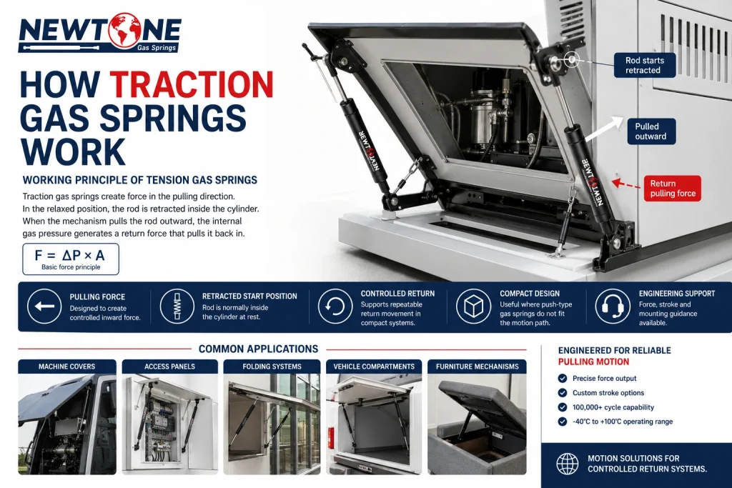
How traction gas springs work is simple in principle: they generate force in the pulling direction instead of the pushing direction. In the relaxed position, the piston rod is normally retracted inside the cylinder; when the application pulls the rod outward, the spring stores energy and then tries to pull the rod back in.
That reverse action makes traction gas springs useful in mechanisms where a standard compression gas spring would push the wrong way. Think of a retractable machine guard, a folding furniture system, a return-assisted access panel, or a compact mechanism that needs controlled inward motion rather than outward lift. The question is not only “how many Newtons?” The more important first question is: which direction does the mechanism need the spring to work?
- 1 What Is a Traction Gas Spring?
- 2 How Traction Gas Springs Work Internally
- 3 Why a Traction Gas Spring Starts Retracted
- 4 Traction Gas Springs vs Compression Gas Springs
- 5 Formula Block: The Force Behind How Traction Gas Springs Work
- 6 Worked Example: Pulling a Moving Panel Back Into Position
- 7 Common Specification Mistakes With Traction Gas Springs
- 8 Mounting Guidance for Tension Gas Springs
- 9 Where Traction Gas Springs Are Used
- 10 Material, Temperature and Life Considerations
- 11 Why Source Traction Gas Springs from Newtone?
- 12 How Traction Gas Springs Work in Specification Decisions
- 13 Frequently Asked Questions About Traction Gas Springs
- 14 Final Engineering Takeaway
What Is a Traction Gas Spring?
A traction gas spring is a pull type gas spring designed to create tension force. It is also commonly called a tension gas spring or reverse action gas spring. The naming changes from market to market, but the engineering idea is the same: the spring helps pull a moving part back toward its starting position.
In a standard compression gas spring, the rod wants to extend. That is why it can help lift a hatch, bonnet, lid or access cover. In a traction gas spring, the rod starts retracted and wants to return inward after being pulled out. This makes it useful when the available space, hinge direction or motion path calls for a pulling force.
For a designer, the first selection decision is therefore not force. It is force direction. If the spring must push a part open, compression is usually the starting point. If the spring must pull a part closed, retract a mechanism, maintain tension or assist return movement, traction is usually the correct family.
How Traction Gas Springs Work Internally
How traction gas springs work internally depends on a reverse-action layout that makes the rod prefer the retracted position. When the rod is pulled outward by the application, the internal gas volume and piston arrangement create a resisting force. When the external load is reduced, that stored energy pulls the rod back into the cylinder.
The practical result is easy to recognize on the machine: instead of helping a lid rise by pushing it open, the traction gas spring pulls the mechanism toward a return position. The user or mechanism extends the spring; the spring then supplies the inward return force.
This is why traction gas springs are often selected where a panel falls downward and needs controlled assistance returning upward, or where a compact mechanism needs a pull-in element that does not require a separate cable, pulley or exposed coil spring.
Why a Traction Gas Spring Starts Retracted
The retracted starting position is the detail that confuses many first-time users. A traction gas spring is not a weak compression spring installed backward. It is built so that its natural force direction is inward. The rod is already inside the cylinder when unloaded, and the mechanism must pull it out to store energy.
That matters during design. If an engineer models the spring as if it starts extended, the geometry can look correct on screen but fail in the first prototype. The spring may bottom out before the mechanism reaches its stop, or it may pull in the wrong part of the motion curve.
A practical way to check the design is to draw the mechanism in both end positions and mark the spring length in each. The traction spring should be shorter in its relaxed or return position and longer in the pulled-out position. If the drawing shows the opposite, the application is probably being specified as a compression problem by mistake.
Traction Gas Springs vs Compression Gas Springs
The difference is force direction. A compression gas spring pushes outward; a traction gas spring pulls inward. This sounds basic, but it changes the whole mounting strategy.
| Design question | Compression gas spring | Traction gas spring |
|---|---|---|
| Natural rod position | Extended | Retracted |
| Force direction | Pushes outward | Pulls inward |
| Typical use | Lift support for lids, hatches and covers | Return support, tensioning and pull-in motion |
| Main specification risk | Too much lift force or poor hinge moment arm | Wrong start position, wrong stroke or wrong force direction |
If the application needs to hold a heavy lid open, compression is often the cleaner answer. If the application needs to pull a component back, keep a linkage under tension or support a downward-opening flap, traction deserves review.
Formula Block: The Force Behind How Traction Gas Springs Work
The internal force principle of a gas spring can be simplified as:
F = ΔP × A
Where F is spring force, ΔP is the pressure difference across the effective area, and A is the effective area. For rod-based gas spring calculations, area can be estimated with:
A = π × d² ÷ 4
Example: assume a traction gas spring has an effective rod diameter of 8 mm (0.31 in). The rod area is:
A = 3.1416 × 8² ÷ 4 = 50.3 mm²
50.3 mm² equals 0.0000503 m². If the effective pressure difference is approximately 4 MPa, or 4,000,000 Pa, then:
F = 4,000,000 × 0.0000503 = 201 N
201 N is approximately 45 lbf. If the mechanism uses two matched traction gas springs, the total theoretical pull support would be about 402 N (90 lbf), before accounting for friction, linkage losses and geometry.
This example explains the principle, not a universal selection value. The final spring force must be checked against the actual mounting geometry, moving mass, stroke, end positions and required user effort.
Worked Example: Pulling a Moving Panel Back Into Position
Consider a compact industrial panel weighing 12 kg (26 lb). Its weight is:
W = m × g = 12 × 9.81 = 117.7 N (26.5 lbf)
If the design uses two traction gas springs only to assist return movement, not carry the full load vertically, the required spring force may be lower than the total panel weight. If the design review estimates a required assisted return force of 220 N (49 lbf), then each spring carries:
F_each = F_total ÷ n = 220 ÷ 2 = 110 N (25 lbf)
From there, the engineer checks whether the selected stroke can cover the full movement. Stroke is:
Stroke = Extended length − Compressed length
If the traction spring is 360 mm (14.2 in) when pulled out and 240 mm (9.4 in) when retracted, the usable stroke is:
360 − 240 = 120 mm (4.7 in)
If the moving pivot travels 135 mm (5.3 in), that spring will not work even if the force is correct. Stroke and end position must be right before the Newton value means anything.
Common Specification Mistakes With Traction Gas Springs
The most common mistake is treating a traction gas spring like a compression gas spring with the drawing flipped. That shortcut usually creates one of three problems: wrong force direction, wrong relaxed length or wrong stroke.
We often see this at the first-article stage. An OEM will send a linkage that looks correct dimensionally, but the spring position shows the rod extended in the supposed rest position. The force number may be reasonable, yet the mechanism is asking the spring to behave opposite to its actual working principle. Once the end positions are redrawn around the retracted start condition, the problem becomes obvious.
Other mistakes are more mechanical. Side-load from misaligned pivots can shorten service life. Oversizing the force can make the mechanism feel harsh and can increase bracket strain. Undersizing the stroke can cause the spring to bottom out before the panel reaches its end stop. None of these are solved by simply adding more Newtons.
Mounting Guidance for Tension Gas Springs
Traction gas springs should be mounted so the force line stays as axial as possible through the full movement. The rod should not be used as a guide rail. If the moving part creates side force, add proper hinges, sliders or pivots so the gas spring only sees tension along its own axis.
End fittings matter here. Ball sockets allow angular movement and are useful where the pivot angle changes through the stroke. Eyelets can be suitable for simpler linkages, provided both pivots stay in the same plane. Brackets should be rigid enough to avoid twisting under repeated load.
For paired springs, use force-matched parts from the same specification and production batch where possible. Newtone manufactures to a ±5% force tolerance, but pairing from mixed batches can still create uneven feel in sensitive mechanisms. On a wide panel, that imbalance may show up as one-sided wear before it shows up as an obvious functional failure.
Where Traction Gas Springs Are Used
Traction gas springs are selected where a pulling or return force is more useful than a push force. Typical applications include folding furniture systems, retractable panels, machine guards, medical equipment sections, access flaps, vehicle compartments, lightweight ramps and technical covers.
They are also useful when the packaging space does not allow a conventional compression gas spring to sit at the correct angle. In compact assemblies, a traction gas spring can sometimes solve a routing problem that would otherwise need a linkage, cable or exposed mechanical spring.
The best applications are those where the moving part has a repeatable path, the pivots can stay aligned, and the design team can define both end positions clearly. The more uncertain the geometry, the more important it is to review the spring with a drawing rather than choosing by force alone.
Material, Temperature and Life Considerations
Most indoor and general industrial traction gas spring applications can use a black nitrided rod with HNBR sealing. For Newtone production, black nitriding provides a hard rod surface of 900–1000 HV with a typical treatment depth of 20–30 µm, while HNBR seals support resistance against UV and ozone exposure.
For humid, coastal, marine, food-related or washdown environments, stainless steel should be reviewed. Stainless is not automatically required for every traction gas spring, but it becomes important when corrosion at the rod surface could damage the seal over time.
Temperature also affects gas spring force. A practical approximation is:
F_T ≈ F_20 × [1 + 0.003 × (T − 20°C)]
That means force changes by about 0.3% per °C. A 200 N (45 lbf) spring at 20°C (68°F) may feel weaker in cold conditions and stronger near heat. Newtone’s operating range is −40°C to +100°C (−40°F to +212°F), but the correct force should still be specified for the real working environment.
Why Source Traction Gas Springs from Newtone?
Manufacturer, Not Distributor
Newtone manufactures gas springs in Turkey and supplies OEM and aftermarket customers in more than 60 countries.
Controlled Force Tolerance
Gas springs are produced with ±5% force tolerance, supporting more predictable paired-spring behavior and repeatable production builds.
Application Review
Engineering support is available for force direction, stroke, mounting points, end fittings and material selection before production.
Built for Industrial Use
Options include standard, stainless steel, locking and custom gas spring configurations depending on the application requirement.
How Traction Gas Springs Work in Specification Decisions
The working principle should guide the specification sequence. First, confirm that the required motion is pull-in, return or tension support. Second, define the two end positions and check stroke. Third, estimate the required force at the real mounting angle. Fourth, choose end fittings that avoid side-load. Only after those checks should the final force, material and production tolerance be confirmed.
If the mechanism is safety-related, frequently accessed or used near people, do not rely on force alone to hold a position. In some applications, a locking gas spring, mechanical latch or secondary stop may be required. The gas spring can assist motion, but the safety function must be designed deliberately.
Frequently Asked Questions About Traction Gas Springs
How do traction gas springs work?
Traction gas springs work by producing force in the pulling direction. In the relaxed position, the rod is retracted inside the cylinder; when the mechanism pulls the rod outward, the internal gas pressure creates a return force that pulls it back in.
What is the difference between a traction gas spring and a compression gas spring?
A compression gas spring pushes outward, while a traction gas spring pulls inward. Compression springs are used when a panel needs lift support; traction springs are used when a mechanism needs controlled return, tension, or pull-in force.
Are traction gas springs the same as tension gas springs?
Yes. In most industrial use, traction gas springs, tension gas springs and pull type gas springs refer to the same product family: gas springs designed to create pulling force instead of pushing force.
Where are traction gas springs used?
Traction gas springs are used in retractable mechanisms, folding panels, machine covers, medical equipment, furniture systems, vehicle compartments and applications where a controlled pulling or return movement is required.
What information is needed to specify a traction gas spring?
To specify a traction gas spring, engineers should define the required pulling force, stroke, extended and compressed lengths, mounting points, end fittings, operating temperature, cycle expectation and whether corrosion resistance or locking is required.
Final Engineering Takeaway
Traction gas springs are not simply standard gas springs installed in reverse. They are designed around a different force direction: the rod starts retracted, extends under external pull and then generates return force toward the cylinder. Get that principle right, and the rest of the specification becomes much clearer.
For OEM engineers, the correct review starts with motion direction, end positions, stroke, mounting alignment and required pulling force. Newtone can support this review with custom sizing, matched force production and material options for industrial, furniture, vehicle and equipment applications.