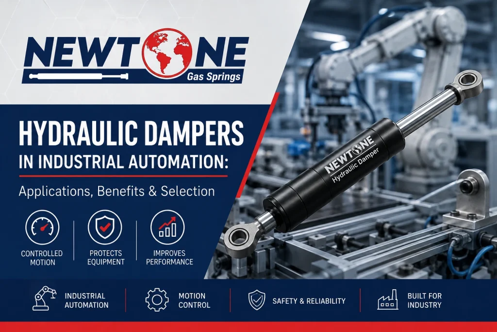
Sizing deceleration for robotic arms, conveyor pallets, and CNC transfer systems — from kinetic energy to orifice, not a guessed catalog curve.
Hydraulic dampers for industrial automation absorb the kinetic energy of a moving mass — a robotic arm, a conveyor pallet, a CNC slide — and convert it to heat by forcing oil through a metered orifice, bringing that mass to a smooth stop instead of a hard one. They don’t push or lift. That’s a gas spring’s job. Mixing the two up on a bill of materials is one of the more expensive mistakes we see cross our desk, and it’s usually caught after the first bent bracket, not before.
Picture a pick-and-place transfer line running 40 cycles a minute. Each pallet arrives at the stop station carrying a 45 kg (99 lb) fixture at roughly 0.5 m/s (20 in/s). Without controlled deceleration, that mass hits the hard stop directly — bent locating pins, loosened fasteners, and a mechanical stop that needs replacing every few months. A correctly sized hydraulic damper absorbs that energy over the last 20–30 mm of travel instead. This page is for the automation OEM engineer or integrator specifying that damper, not just buying whatever fits the mounting hole.
How Hydraulic Dampers for Industrial Automation Actually Slow a Load
A hydraulic damper is a closed cylinder: oil chamber, piston with orifices or a valve, rod, and seals. As the rod is pushed in, oil is forced through the restricted orifice from one side of the piston to the other. That restriction is what creates resistance — and because fluid flow through a small orifice resists in proportion to speed, the damper pushes back harder the faster the load is moving and eases off as the load slows. That’s the useful property gas springs don’t have: a gas spring’s force is set mostly by internal pressure and barely changes with speed, while a damper’s resisting force is speed-dependent by design. Newtone’s full hydraulic dampers range covers both extension and compression damping configurations for this kind of duty.
This matters for line design. A gas spring holds a door open at a given angle regardless of how fast you swing it there. A damper does nothing until something is moving, and its job is entirely to manage that motion — quickly at first, gently as it approaches zero.
Sizing Hydraulic Dampers for Industrial Automation: A Worked Example
Viscous damping force:
Fdamp = c × v
where c = damping coefficient (N·s/m), v = rod velocity (m/s). Resisting force rises with velocity — this is the relationship that separates a damper from a spring.
Take the transfer-line pallet from above: mass m = 45 kg (99 lb), approach velocity v = 0.5 m/s (19.7 in/s), usable damper stroke = 25 mm (1 in).
Step 1 — kinetic energy to absorb:
KE = ½ × m × v² = ½ × 45 × 0.5² = 5.6 J
Step 2 — average force needed over the stroke:
Favg = KE ÷ stroke = 5.6 ÷ 0.025 = 225 N (50.6 lbf)
Step 3 — back-solve the damping coefficient using the average velocity across a linear deceleration (vavg ≈ v ÷ 2 = 0.25 m/s):
c = Favg ÷ vavg = 225 ÷ 0.25 = 900 N·s/m (5.1 lbf·s/in)
That coefficient is what you hand a damper supplier — not the pallet weight alone. The orifice size sets the coefficient: a larger orifice lowers c (faster stop, more residual shock at contact); a smaller orifice raises c (gentler stop, but more heat generated per cycle, which matters on high-frequency lines). Apply a safety-factor surcharge of roughly 1.15–1.3 on the calculated force if the line speed is expected to drift upward over the product’s life — cheaper to spec for it now than to requalify a damper later. When pallet weight or approach speed varies meaningfully across product changeovers, this single-point calculation isn’t enough on its own; that’s exactly the gap covered below.
Why Off-the-Shelf Damping Curves Miss Line-Speed Variability
Most damper catalogs publish a single force-at-rated-speed curve, and most specs get written against that one number. The problem: real automation lines rarely run at one constant speed. A servo-driven transfer changes acceleration profiles between product SKUs; a pneumatic actuator’s approach speed shifts with air pressure and temperature; a conveyor’s pallet mass changes with what’s loaded on it. A damper sized tightly to one nominal speed can be under-damped at a faster changeover speed (hard contact, bracket fatigue) or over-damped at a slower one (sluggish cycle time, unnecessary heat).
An automation OEM we worked with had specified a fixed-orifice damper for a transfer station sized to the catalog’s rated 250 N (56 lbf) energy absorption at nominal line speed. It held up fine in qualification. In production, a changeover to a heavier fixture pushed the approach velocity higher during that product’s run, and the fixed orifice couldn’t shed the extra energy — the line started chattering at the stop station and two brackets cracked within a month. Recalculating from actual peak velocity (not the nominal spec) and moving to a self-compensating damper — one that adjusts its effective orifice area across a speed range rather than holding a single fixed setting — solved it without redesigning the stop station. The lesson: size to the worst-case velocity your line will actually see, not the number on the datasheet cover page.
Choosing a Damper Class for Your Application
Adjustable
An external screw sets the orifice opening manually. Good fit when line speed is fixed and known at commissioning, and you want the option to fine-tune damping feel once during setup. Lowest cost of the three classes.
Self-compensating
The damper adjusts its effective flow area automatically as approach speed varies within a designed range. Right choice for multi-SKU lines, changeover-heavy cells, or any station where the incoming mass or velocity isn’t constant.
Heavy-duty
Built for high single-impact energy — crane end-stops, large gantry axes, heavy tooling decks. Bigger bore, more oil volume, and a cooling reserve for repeated high-energy cycles without the internal temperature climbing enough to thin the oil and soften the response.
Common spec mistake: sizing to the datasheet’s rated energy figure at nominal speed instead of the actual worst-case approach velocity the station will see across every product variant it runs. The fix costs nothing at spec time — a wrong damper in the field costs a line stoppage.
Cold Storage, Wash-Down, and Temperature Limits
Damping performance depends on oil viscosity, and viscosity is temperature-sensitive in a way gas spring force isn’t. Below the oil’s pour point, flow through the orifice effectively stops and the damper locks up or loses controlled resistance — a real constraint on freezer-adjacent automation, cold-chain packaging lines, or outdoor-adjacent equipment in northern climates. Newtone’s standard hydraulic dampers are rated across −40°C to +100°C (−40°F to +212°F), which covers cold-storage automation without a special oil fill, but always confirm the duty-cycle temperature at the damper itself, not just ambient — a station running 40+ cycles a minute can run meaningfully warmer at the damper body than the room around it.
Service life follows a similar logic to any wear component: Service years ≈ Rated cycles ÷ cycles-per-day ÷ 365. At 100,000+ minimum rated cycles and 40 cycles/minute across two shifts (roughly 38,400 cycles/day), that’s a rough ceiling near three days of continuous nominal-speed operation before a rated-life review — a number worth checking against your actual duty cycle rather than assuming, since most stations don’t run at nominal speed continuously. High-frequency stations should be reviewed against actual cycles-per-day, not nameplate figures, and the dominant wear driver is almost always seal degradation from sustained internal heat, not mechanical fatigue of the housing.
Mounting for Consistent Damping Behavior
A damper is only as good as its geometry. A few points that hold regardless of application:
- Axial load only. Dampers, like gas springs, are designed for straight-line force along the rod axis. Any lateral load from a misaligned bracket accelerates seal wear and changes the effective damping curve over time — the damper starts feeling “soft” well before it’s actually failed.
- End fitting selection matters. A ball-socket or eyelet end that tolerates slight angular misalignment keeps the rod from being side-loaded as the mechanism travels through its arc — important on any pivoting station, less so on a purely linear stop.
- Mount position sets the effective stroke. Where the damper contacts the moving mass relative to its own stroke determines how much of the deceleration happens in the damper versus at a hard mechanical stop behind it — moving the contact point earlier in the travel gives the damper more distance to work with and lowers the required force for the same kinetic energy.
- Don’t confuse this with a locking function. A damper controls motion; it doesn’t hold position. If your station also needs to hold a panel or arm open for maintenance access, that’s a job for a locking gas spring, not a damper — the two are often specified together but solve different problems.
For a broader look at how damping fits alongside the other gas spring types Newtone builds — standard, locking, traction, stainless — see our types of gas springs guide, which covers when each configuration is the right call.
Where Hydraulic Dampers Show Up on Automation Lines
Robotic End-of-Stroke Cushioning
Mounted at the limit of a linear actuator or joint travel to absorb the last few millimeters of motion before a hard mechanical stop, protecting the joint bearings and end-effector from repeated impact loading.
Conveyor & Pallet Transfer Stops
Positioned at fixed stop stations to bring pallets or fixtures to a controlled halt at speed, reducing part shift, fastener loosening, and stop-block wear on high-cycle lines.
CNC Tooling Deceleration
Used on tool-change arms and indexing tables where a component must decelerate rapidly into position without overshoot, keeping repeat positioning accuracy within tolerance cycle after cycle.
Sourcing Hydraulic Dampers From Newtone
FAQ
What’s the difference between a hydraulic damper and a gas spring?
A gas spring stores energy under gas pressure to push, lift, or hold a load open. A hydraulic damper does the opposite job: it absorbs kinetic energy from a moving mass and dissipates it as heat through oil forced across an orifice, controlling deceleration rather than generating force. Some applications, like soft-close cabinet flaps, use a damper alongside a spring — the spring provides the motion, the damper controls its speed.
Do I need a damper or a locking gas spring for my station?
If the requirement is controlling how fast something moves or stops, that’s a damper. If the requirement is holding a panel, arm, or cover firmly open at full extension — for a maintenance access point, for example — that’s a locking gas spring. The two are frequently specified together on the same mechanism but answer different questions.
How do I calculate the damping force I need?
Start from the kinetic energy of the moving mass at its approach velocity, divide by the usable stroke to get an average force, then back-solve the damping coefficient from that force and the average velocity. See the worked example above for the full calculation with real numbers — and apply a safety-factor surcharge if line speed is likely to increase over the equipment’s life.
Can hydraulic dampers work in cold storage or freezer-adjacent automation?
Yes, within the oil’s rated temperature range — Newtone’s standard hydraulic dampers are rated −40°C to +100°C (−40°F to +212°F). Below a given oil’s pour point, flow through the orifice slows or stops and damping performance degrades, so cold-chain applications should always confirm duty-cycle temperature at the damper body, not just room ambient.
Should I choose an adjustable, self-compensating, or heavy-duty damper?
Adjustable suits a fixed, known line speed set once at commissioning. Self-compensating is the right call when approach speed or mass varies across product changeovers, since it adjusts its effective orifice automatically. Heavy-duty is for high single-impact energy applications like large gantry axes or crane end-stops rather than typical automation transfer stations.
Getting the Damper Spec Right the First Time
The