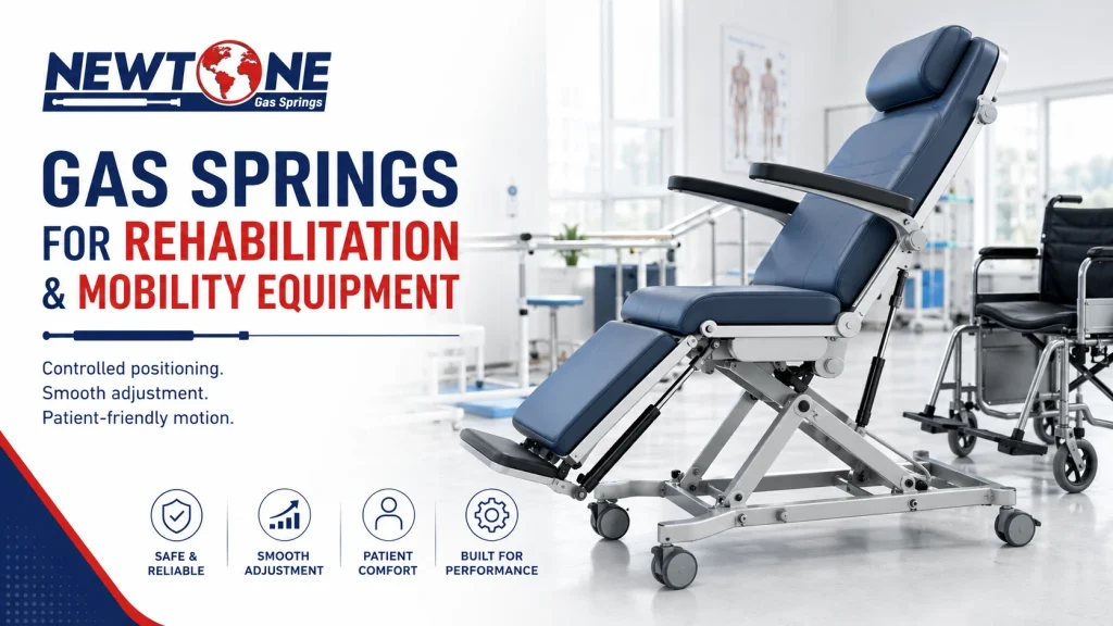
Rehabilitation & Mobility Equipment — Controlled User-Assist Motion
Gas Springs for Rehabilitation and Mobility Equipment
How to specify gas springs for safe, smooth and controllable movement in rehab chairs, mobility seating, leg supports and assistive equipment.
50–450 N
Common planning range for many rehab and mobility adjustment modules, equal to 11–101 lbf
±5%
Newtone force tolerance for consistent paired-spring behavior
100,000+
Minimum cycle capability for Newtone gas springs
−40°C to +100°C
Operating range, equal to −40°F to +212°F
Why Gas Springs for Rehabilitation and Mobility Equipment Need Controlled Motion
Gas springs for rehabilitation and mobility equipment need controlled motion because the person operating the device may not have normal strength, balance or reaction time. A part that feels acceptable on a workbench can feel too aggressive when it is connected to a patient-facing seat, backrest or leg support. Typical applications include rehab chairs, adjustable therapy devices, mobility seating, tilt-in-space modules, transfer chairs, leg rests, arm supports, head supports, mobility scooter seats and service-access panels on assistive equipment. In each case, the gas spring reduces effort and helps hold a position, but the movement must remain predictable. The design question is not only “can the gas spring lift this section?” The better question is “can the intended user or caregiver control this movement through the whole stroke?” That is where force, stroke, pivot position, damping, release handle location and locking behavior must be reviewed together.The Correct Force Is the Force a Weak User Can Control
The correct force is the force a weak user can control, not the highest force that holds the part open. This is the most important difference between rehabilitation equipment and ordinary industrial covers. A gas spring that over-assists a backrest or leg support can create a harsh release feel. The user may press the lever and the section may move faster than expected. A caregiver may then fight the mechanism instead of being helped by it. Too much force can also make the section difficult to return to its closed or lowered position. In one first-article review, a mobility equipment OEM approached the design as if “stronger” meant “safer.” The first force estimate supported the moving section, but the release and return effort were not comfortable for the intended user group. Reviewing the moment arm, handle location and handling-force target led to a lower, more controllable force and a cleaner locking gas spring layout. The lesson was simple: in assistive equipment, support force and user control must be designed together.Where Gas Springs Are Used in Rehabilitation and Mobility Equipment
Gas springs are used in rehabilitation and mobility equipment wherever a moving section needs assisted lifting, controlled lowering or position holding. The most common locations are seat tilt systems, backrest recline mechanisms, leg supports, arm supports, therapy table sections, standing-assist modules, wheelchair-style seating functions and mobility scooter seat bases. Standard compression gas springs are useful when the part needs lift support but does not need to lock at intermediate positions. Locking gas springs are better when the user must hold a selected angle, such as a backrest, seat tilt or leg support position. Hydraulic dampers can be reviewed when the main problem is speed control rather than load support. The same device may use more than one motion-control product. A seat module may need a locking gas spring for positioning, a standard gas spring for a service cover and a damper for controlled lowering. That is why component selection should follow the function of each moving part instead of treating the whole device as one gas spring application.Handling Force Calculation for Rehab and Mobility Adjustments
The handling force relationship helps estimate how much effort a user or caregiver may feel when closing, lowering or adjusting a gas-spring-assisted section. It is not a replacement for full geometry review, but it is useful because this topic is about controllability, not only load support. Formula: F_close = (n × F1 × r) ÷ L_lid Where: F_close = approximate handling force felt at the user contact point n = number of gas springs F1 = gas spring force near the extended position r = effective perpendicular moment arm of the gas spring L_lid = distance from pivot to the user handle or contact point Example: a rehabilitation leg support uses one gas spring rated at 180 N (40 lbf). The effective spring moment arm is 70 mm (2.8 in), and the caregiver applies force at a handle 320 mm (12.6 in) from the pivot. F_close = (1 × 180 × 70) ÷ 320 F_close = 39 N (9 lbf) Now consider the same mechanism with a 250 N (56 lbf) spring because someone wanted the support to feel “stronger.” F_close = (1 × 250 × 70) ÷ 320 F_close = 55 N (12 lbf) The second version may still be mechanically possible, but it asks the user or caregiver to handle more force. In a normal industrial hatch, that difference may not matter much. In rehabilitation and mobility equipment, it can change whether the adjustment feels smooth, safe and usable. For initial force sizing of a hinged section, the moment balance still applies: F = (W × Lg × cos φ) ÷ (n × r) That formula checks whether the gas spring can support the section. The handling-force check asks whether the human can control it. Both questions matter.Locking vs Non-Locking Gas Springs
Locking gas springs should be reviewed when rehabilitation or mobility equipment needs stable positioning at a selected angle. Backrests, tilt seats, leg supports and adjustable arm sections often need more than simple lift assistance; they need controlled position holding after the user releases the control. A standard compression gas spring is appropriate when the movement only needs assistance or counterbalance. A locking gas spring is appropriate when the section must stay where the user sets it. The release mechanism then becomes part of the design. Its cable route, lever force, handle location and user reach all affect real usability. Locking is not automatically better for every part. If the section only opens for service or storage, a standard gas spring may be cleaner. If the section supports user posture or comfort, locking behavior should be reviewed carefully.Smooth Release Behavior Matters
Smooth release behavior matters because sudden movement can make rehabilitation and mobility equipment feel unsafe even when the force calculation is technically correct. A gas spring may hold the load, but if it releases too quickly or pushes too hard at the wrong angle, the device will feel poorly engineered. Release behavior depends on gas spring force, pivot geometry, friction, damping, user handle position and the weight of the moving section. A short handle can make the same gas spring feel harder to control. A poor pivot location can make the beginning of travel feel too light and the end of travel too heavy. Where movement speed is the main concern, hydraulic dampers may be reviewed alongside gas springs. The gas spring provides assist force; the damper controls velocity. Mixing those two functions correctly can make a rehab mechanism feel calmer and more predictable.Single vs Paired Gas Springs in Mobility Equipment
Single gas springs can work on narrow or compact rehab mechanisms, but paired gas springs are often better for wide seat modules, larger backrests and double-sided leg supports. Two springs spread the load and reduce twisting across the structure. Paired gas springs must be force-matched. If one side is stronger, the moving section may lift unevenly, bind in the frame or create one-sided wear at the brackets. This is especially noticeable in mobility equipment where users feel small differences through the seat or support surface. Newtone controls force tolerance at ±5%, which supports repeatable paired behavior. For OEM production, matched gas springs from the same platform are cleaner than mixing parts that only share a nominal force value. For aftermarket replacement, paired springs should usually be replaced together when motion balance matters.Material and Cleaning Environment
Material selection depends on whether the equipment operates indoors, outdoors, near cleaning chemicals or in high-humidity conditions. For most indoor rehabilitation and mobility equipment, Newtone’s black nitrided rod with HNBR sealing is a strong standard solution. The black nitrided rod has a typical surface hardness of 900–1000 HV and a treatment depth of 20–30 µm. HNBR sealing is standard and is selected for UV and ozone resistance. This combination fits many rehab chairs, mobility seating modules, therapy devices and indoor assistive equipment. Stainless steel gas springs should be reviewed for outdoor mobility equipment, hydrotherapy environments, high-humidity storage, washdown use or devices exposed to cleaning routines that are more aggressive than normal dry indoor use. The fittings and mounting brackets should be reviewed with the same logic. A stainless spring mounted with unsuitable hardware is not a complete corrosion-resistant solution.Mounting Guidance for Rehabilitation and Mobility Equipment
Mounting guidance for rehabilitation and mobility equipment starts with avoiding side-load. Gas springs are designed for axial load. Both pivots should stay in the same plane of motion, and the end fittings should allow the angular movement required by the mechanism. Where geometry allows, mount the gas spring with the rod pointing down in the at-rest or closed position. This helps keep oil near the seal and supports smoother damping. In patient-facing equipment, quiet and consistent movement matters because the user is physically close to the mechanism. Do not use the gas spring as the hard stop unless the design has been reviewed for that purpose. The structure should include a proper stop where needed. Bottoming out a gas spring can create shock loads at the rod, seal and brackets. Release access deserves the same attention as force. A lever that is hard to reach, requires too much grip force or is placed on the wrong side of a transfer chair can make a technically correct gas spring feel wrong to the user.Common Specification Mistakes
The most common mistake is choosing too much force. In rehabilitation and mobility equipment, a stronger gas spring can make a mechanism harder to return, harder to release smoothly and less comfortable for the intended user. The second mistake is selecting by load only. Load support matters, but pivot geometry, handle distance, release behavior and the user’s strength decide whether the mechanism feels usable. A gas spring can pass a static load check and still fail the human-use test. The third mistake is ignoring paired-spring matching. Wide backrests, seat sections and leg supports can feel uneven if the two springs do not behave similarly. Small force differences can become noticeable when the user is sitting directly on the moving structure. Other mistakes include placing the release handle too far from the caregiver’s natural hand position, using a non-locking spring where position holding is required, ignoring cleaning exposure and replacing an original spring by length only without checking force and stroke.Specification Checklist for Gas Springs for Rehabilitation and Mobility Equipment
| Specification point | Why it matters |
|---|---|
| Supported load | Defines the basic force requirement, but does not decide usability by itself. |
| Pivot geometry | Controls leverage, release feel and handling force. |
| Stroke | Must match the required movement without bottoming out. |
| Locking requirement | Needed when a seat, backrest or support must hold selected positions. |
| Release handle location | Determines whether the user or caregiver can operate the system comfortably. |
| Single or paired layout | Wide modules may need matched pairs to prevent twisting. |
| Cleaning environment | Washdown, humidity or outdoor exposure may require stainless steel review. |
| Replacement behavior | Force, stroke and end fittings should be matched, not only overall length. |